Wiring up a Wifi Module ESP-01
April 26, 2020
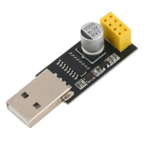
The ESP8266 is an awesome Wi-Fi microcontroller, with full TCP/IP capability. It's very popular among hackers and hundreds of tutorials are available for it. These modules come in a wide variety of models, being the ESP-01 one of the most popular and cheapest.
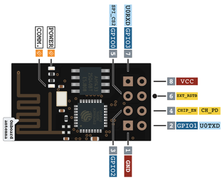
1. GND - Ground2. GPIO2 - General Purpose Input/Output3. GPIO0 - General Purpose Input/Output (Used for boot mode too)4. UXRXD - Receiver (for serial communication)5. U0TXD - Transmitter (for serial communication)6. CH_PD - Chip powerdown7. EXT_RSTB - Reset8. VCC - 3.3v input voltage
I bought one of these amazing modules a few days ago because I want to explore Home Automation and IoT, and while trying to program it I found a lot of confusing information online. This will be my attempt to document how to wire up and program this microcontroller. I'm no expert in electronics, so this is just me following different tutorials and trying to make the best out of them.
Tools
- Multimeter (required to test continuity and verify voltage)
- Wire strippers or an exacto knife
- Soldering Iron + solder
Materials
- ESP-01
- Breadboard
- ESP-01 breadboard adapter; or 2 1x4 male header pins, 1 2x4 female header pin and a 4 x 4 perforated board
- 2 tactile switches
- 1 led
- 3 resistors (I used 1000Ω).
- 20 gauge single wire cables or jumper cables
- 3.3v regulator (see notes)
- A programmer: an Arduino Uno R3 or a USB to TTL serial adapter with 3.3v output
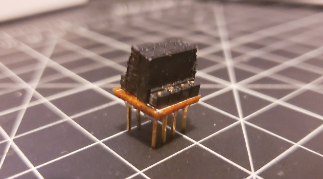
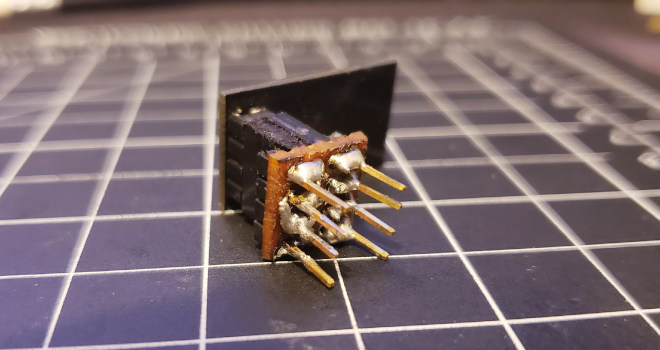
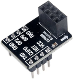
Breadboard Adapter
Sadly, the ESP-01 can't be easily mounted to a breadboard. You need to use an adapter. If you want to go the DiY route, you need to take a 4x4 perforated board and male and female pins (if you don't have a 2x4 female header, you can take 2 1x4 female header and put them together). Solder them as shown in this picture. (each female pin to their corresponding male pin)
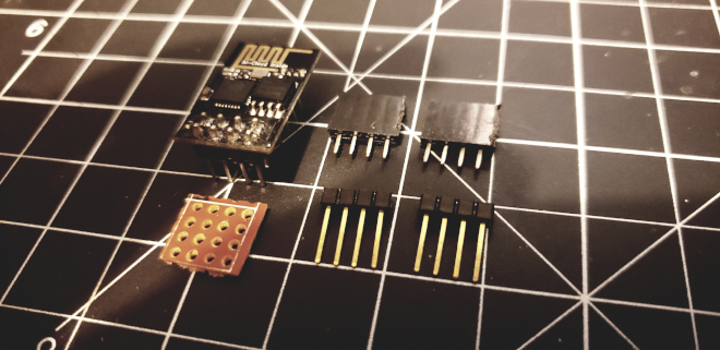
You could also buy an adapter like this instead!
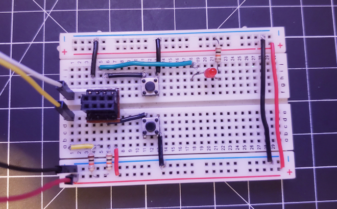
The schematic
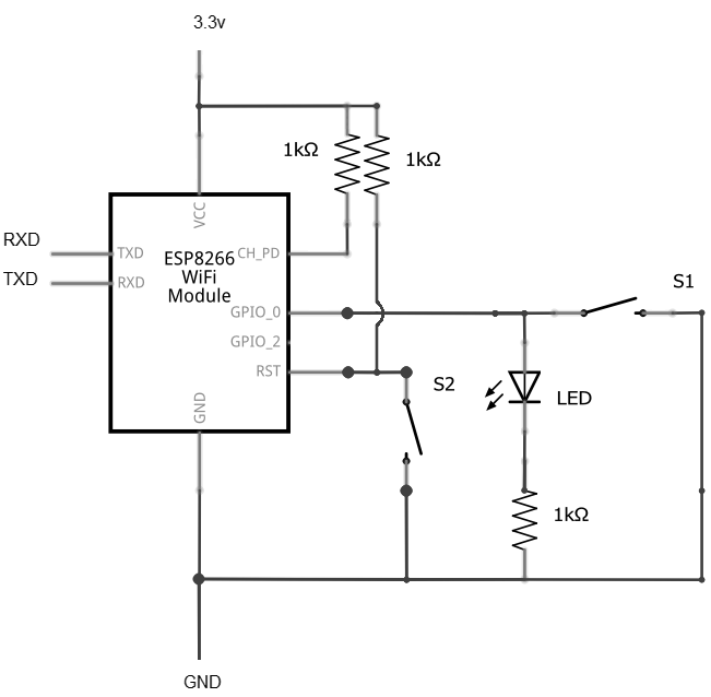
Reproduce this schematic in a breadboard (or in a perforated board if you want to make this permanent. You might need some extra header pins to connect the programmers).
This schematic has two buttons. The bottom one, connects the RST pin to GND when pressed and resets the ESP; and connects the RST to VCC through a pull-up resistor when you release the button. The top button connects GPIO0 to GND through a led and resistor. These two buttons are used to enter all the modes available to the ESP8266.
- Normal execution: No buttons pressed
- Reset microcontroller: Bottom button pressed
- Boot/Flash mode: Both buttons pressed, release the bottom button first and then release the top button
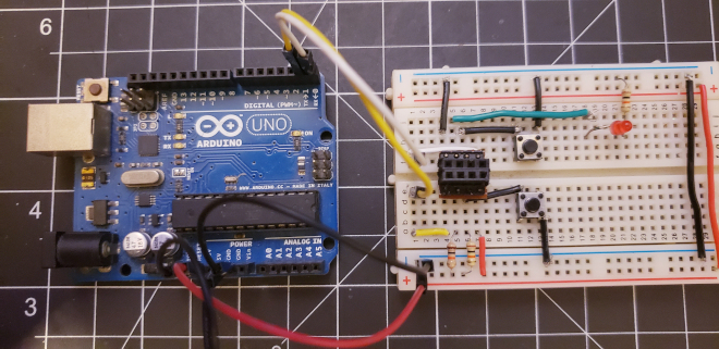
Arduino
The Arduino R3 can be used as a programmer, To connect it to the ESP, connect the following pins. Notice that the ESP-01 uses the 3.3v pin. If you use the 5v pin you will damage the ESP-01 because it does not have an onboard voltage regulator
+---------+---------++ ESP-01 | Arduino |+---------+---------+| GND | GND || TX | RX || RX | TX || VCC | 3.3v |+---------+---------+
Arduino's RESET must be connected to one of the GND pins with a jumper cable
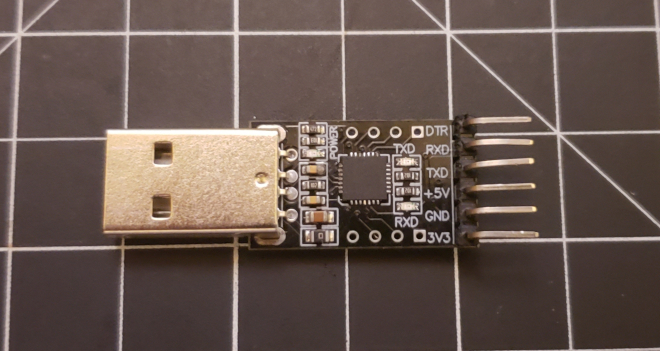
USB to TTL adapter
+---------+----------++ ESP-01 | USB->TTL |+---------+----------+| GND | GND || TX | RX || RX | TX || VCC | 3.3v |+---------+----------+
The process is similar to connecting to an Arduino (the same pin connections), however these adapters might not output the current required by the ESP-01. You might end up requiring an external power source to provide the 3.3 volts. Be sure to read the datasheet of your adapter to know how much current it can provide. The one I'm using outputs 500mA which is enough to program the ESP.
If you require using an external power source, be sure its output is 3.3v using a multimeter. You can achieve 3.3v with either a power regulator like the LM117
Also, it's important that all grounds are connected together (the external power source, the adapter and the ESP-01)
Other programmers
There are some cheap USB to UART programmers that can be turned into programmers. In this video the process is meticulously explained: https://www.youtube.com/watch?v=6uaIWZCRSz8 . It's an interesting alternative and one that I'll be trying in the future
Programming
If you are using a USB to TTL adapter like the CP2102 you need to install the drivers. Refer to the datasheet of your programmer to know if you require drivers or not.
We are going to use the Arduino IDE, which is really easy for novices, but it's also possible to use C language, Basic, Lua or Python to code the ESP-01. Download the Arduino IDE. The latest version available is 1.8.2
Once installed, go to File > Preferences, and in Additional Boards and Managersfield add the URL: http://arduino.esp8266.com/stable/package_esp8266com_index.json.
Then, in Tools > Board > Board Manager, install esp8266 by ESP8266 Community version 2.6.3.
Select Generic ESP8266 Board in Tools > Board, and select the Blink example in File > Examples > 01.Basics. Replace the led pin number from 13 to 2.
int led = 2;void setup() {pinMode(led, OUTPUT);}void loop() {digitalWrite(led, HIGH);delay(1000);digitalWrite(led, LOW);delay(1000);}
Click on the arrow button on the Arduino IDE to upload the program, and when you see this on the console:
Sketch uses 256332 bytes (26%) of program storage space. Maximum is 958448 bytes.Global variables use 26808 bytes (32%) of dynamic memory, leaving 55112 bytes for local variables. Maximum is 81920 bytes.esptool.py v2.8Serial port COM4Connecting........_____
Press both buttons, release the bottom button first, and then release the second button. You'll see the led stay ON, and the blue led onboard the ESP-01 flash. This will be shown in the console:
Chip is ESP8266EXFeatures: WiFiCrystal is 26MHzMAC: 18:fe:34:dc:f6:11Uploading stub...Running stub...Stub running...Configuring flash size...Auto-detected Flash size: 1MBCompressed 260480 bytes to 190665...Writing at 0x00000000... (8 %)Writing at 0x00004000... (16 %)Writing at 0x00008000... (25 %)Writing at 0x0000c000... (33 %)Writing at 0x00010000... (41 %)Writing at 0x00014000... (50 %)Writing at 0x00018000... (58 %)Writing at 0x0001c000... (66 %)Writing at 0x00020000... (75 %)Writing at 0x00024000... (83 %)Writing at 0x00028000... (91 %)Writing at 0x0002c000... (100 %)Wrote 260480 bytes (190665 compressed) at 0x00000000 in 16.6 seconds (effective 125.8 kbit/s)...Hash of data verified.Leaving...Hard resetting via RTS pin...
After a while, the script will be uploaded, and you will have to press the bottom button to reset the ESP and that's it! you should see the led blinking!
Operation
You should now be able to use the ESP-01 as a standalone microcontroller assuming you use a 3.3v power source. The GPIO0 should also be available for use in your code.
There are also some examples available in File > Examples that use the ESP8266 WiFi capabilities, to make your own access points or web clients.